Sensors
The device integrates three sensors, which combined can be used to monitor presence or activity levels in indoor environments:
- A digital ambient-light sensor
- A pyroelectric motion sensor (PIR)
- An ambient-noise level (SPL) sensor
Ambient light sensor
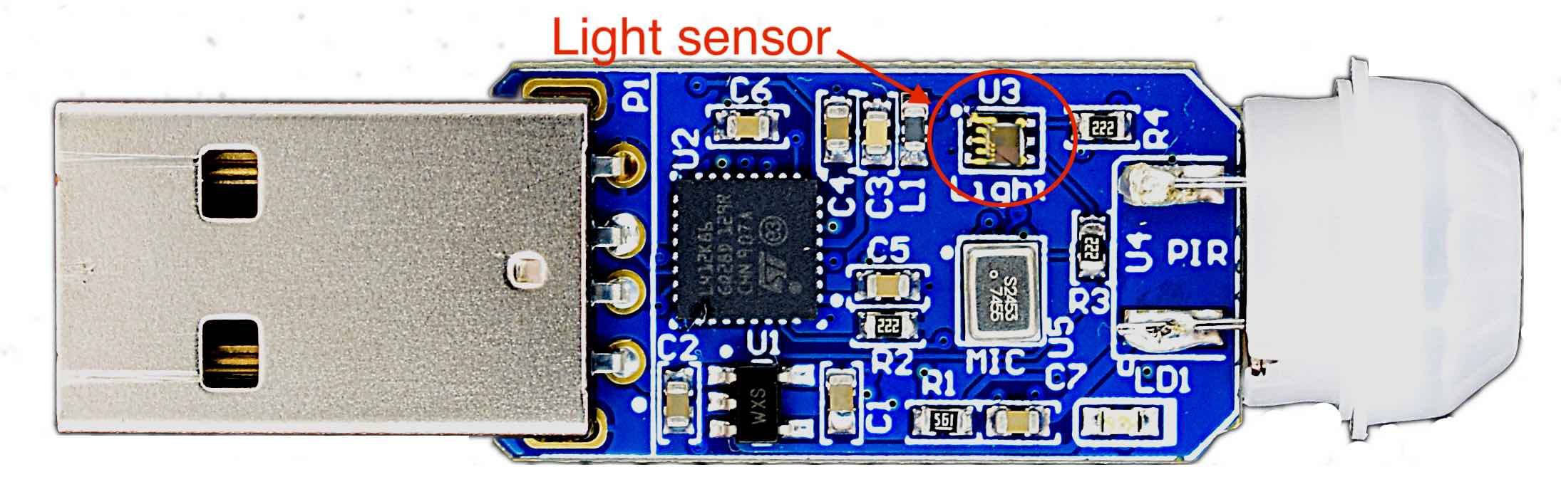
The digital ambient light sensor is a LiteOn Optoelectronics LTR-303ALS-01 (datasheet here)
The LTR-303ALS-01 is a dual-channel I2C digital light sensor. This sensor converts light intensity to a digital output signal. It provides a linear response over a wide dynamic range from 0.001 lux to 64k lux.
The sensor has 6 configurable gains (1X, 2X, 4X, 8X, 48X and 96X) which are automatically adjusted on the firmware, so the output is continually shown in the entire usable range.
The sensor integrate two photo-diodes (in the visible and infrared regions), which are used by the internal uThing::MNL algorithm to output a luminosity value close to the human vision response (rejecting infrared light).
Output values
The sensor output is provided in [lux] units, as in a "lux-meter" or "light-meter" used in photography and indoor illumination.
The [lux] is a measure of the illuminance, measuring the light energy per unit of area (luminuous flux more precisely).
lux output
This value can vary on a very wide dynamic range, and the output of the sensor depends on the spectral distribution of the received light (color temperature).
As a rough guide, here is a table with examples of some illuminance levels:
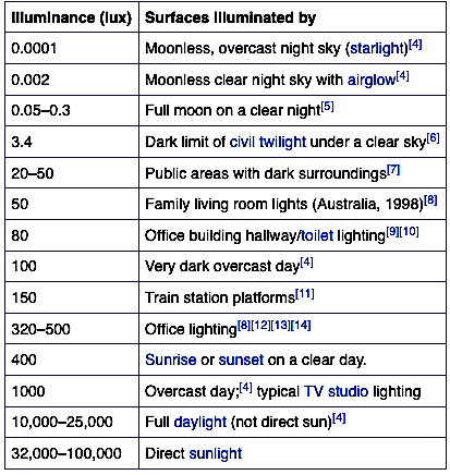
(source: wikipedia)
On every reporting message, the device sends two values:
- The last measured illuminance
- An average value (exponential moving average), useful to quickly see a smoothed value, or as a dynamic reference for quickly changing values (i.e. moving objects close to the sensor).
Output example:
"light": {
    "last": 40.97,
    "average": 65.28
}
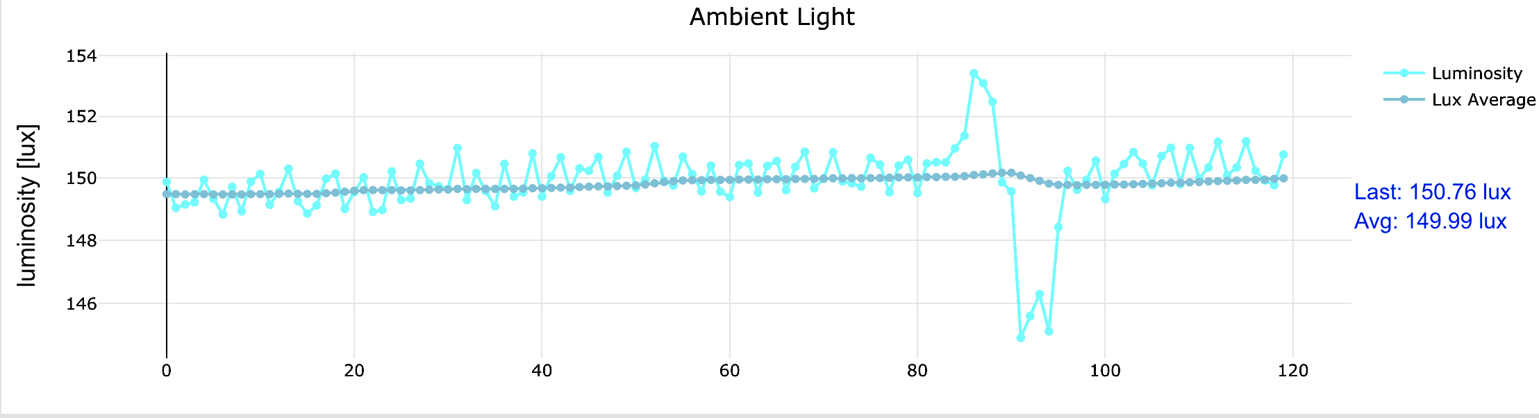
The image below shows a captured signal with under normal office light conditions (sensor is not pointing directly to the light source). The instant values captures a shadow from a moving person:
Sensor orientation
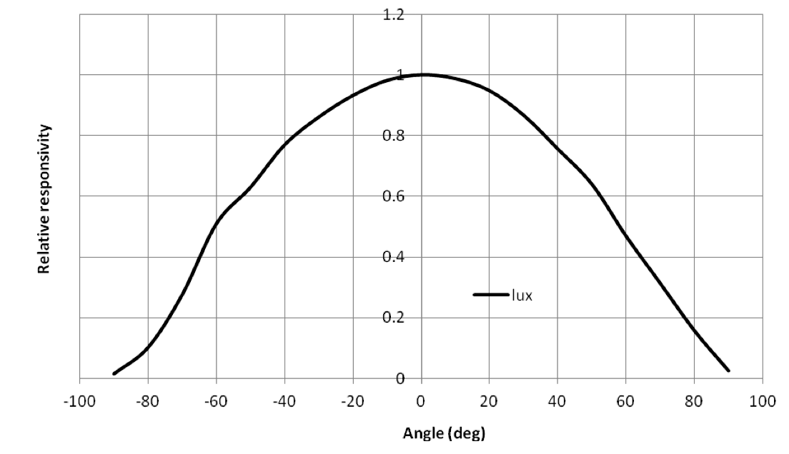
As expected, the output of the light sensor depends on the angle of the incident light (a light beam coming from the back-side of the uThing::MNL can't be seen by the sensor). Therefore is important to take into consideration the installation position and potential obstacles that can block the incident light.
The viewing angle of the sensor is shown below:
Motion sensor
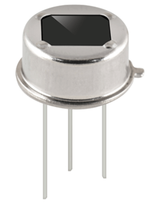
The motion sensing is based in a dual-element pyroelectric sensor (PIR). The picture below shows the sensor in a metallic can package. Integrating two sensing elements along with the electronics for the signal processing and a infrared filter window.
Pyroelectric effect
The functioning principle of PIR sensors is based on the Pyroelectric Effect. Pyroelectricity can be described as the ability of certain materials to generate a temporary voltage when they are heated or cooled. With an appropriate arrangement of amplifying, filtering and processing electronics along with a special lens, this effect can be used to detect motion of objects above room temperature (persons, animals, etc.).
Fresnel lenses
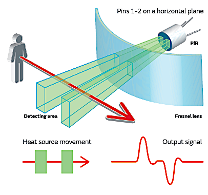
Each pyroelectric transducer can detect small temperature variations, but in order to detect a person moving across the sensor's field of view, a Fresnel lens is used to split the sensitive area in smaller sub-regions. The optical design of this lens will result in different fields of view and maximum detection distance.
The Fresnel lens help to increase the variation of the infrared energy seen by the dual segments of the sensor when a warmer object cross along the areas defined by the lens as explained on the diagram below:
In order to maximize the flexibility for different applications and environments, the uThing::MNL comes with 2 different interchangeable lenses:
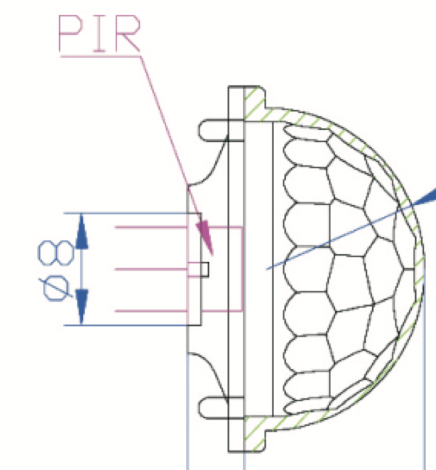
Model F-001:
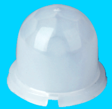
Type: Dome
- Dome (half sphere) shape
- Overall size: 11.8 x 11.8 x 9.73 mm
- Max. detection distance: 5 meter (15 feet)
- Viewing angle: 60º
Model F-002:
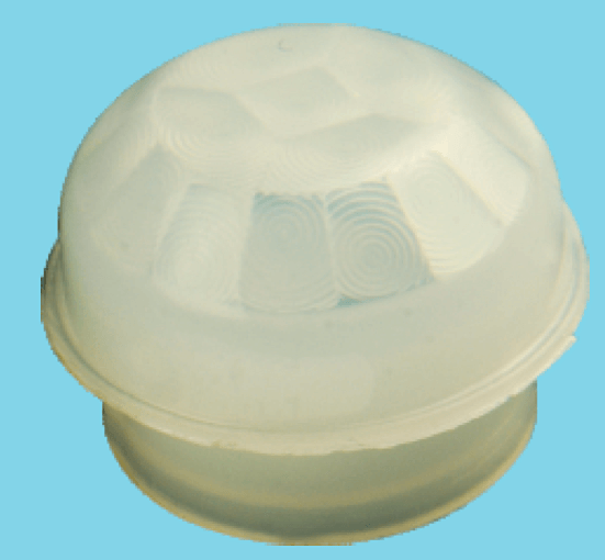
Type: Angled
- Angled shaped (flat top)
- Overall size: 13.6 x 13.6 x (4.0 + 6.0) mm
- Max. detection distance: 5 meter (15 feet)
- Viewing angle: 120º
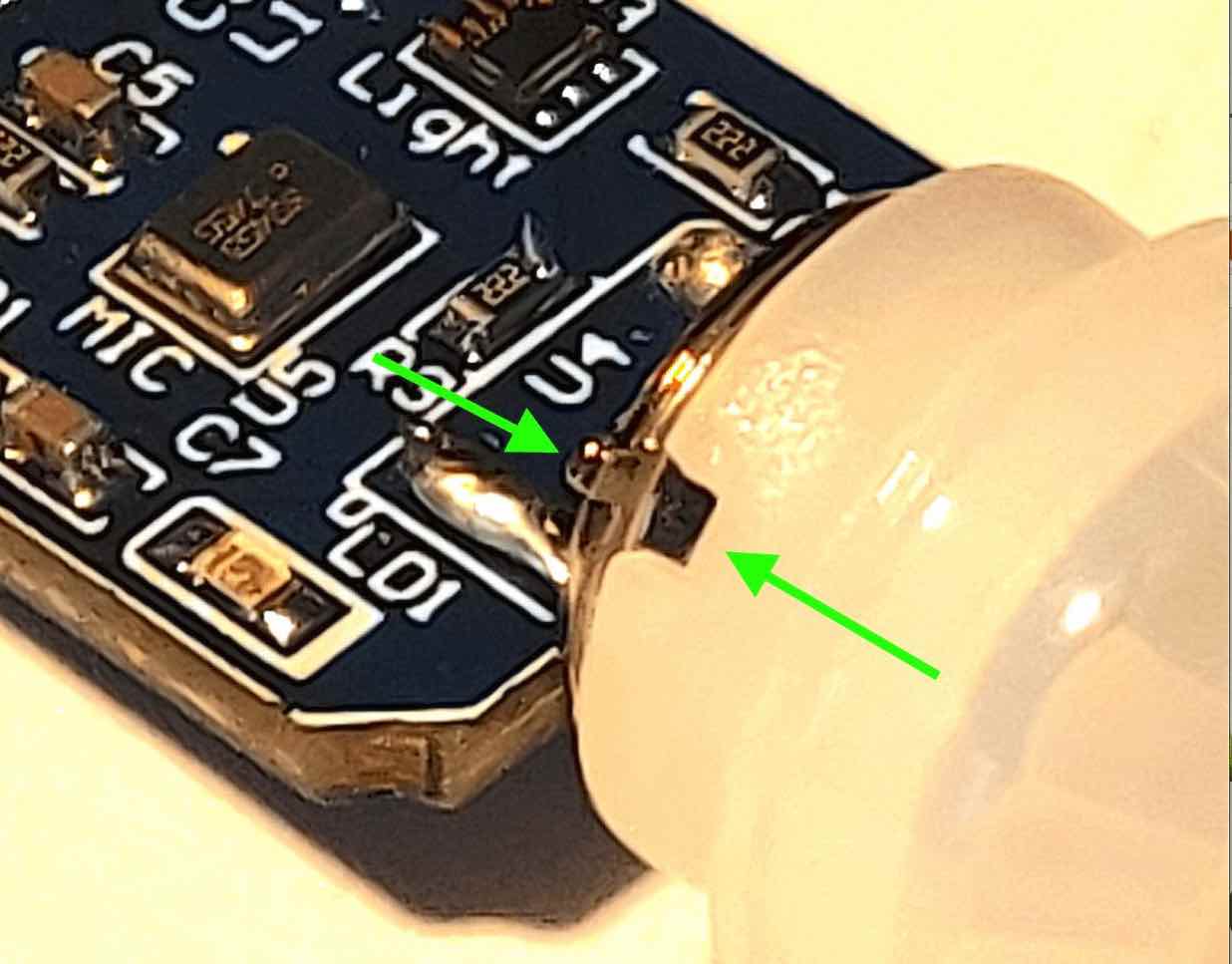
Correct insertion
For best performance, please make sure that the slot on the lens is aligned with the feature on the sensor so the lens can be pushed until the end position, ensuring the right focal distance.
Which one is better?
The detection distance and angle will depend on the specific installation conditions and environment (ambient temperature, what the person walking close-by is wearing, etc.). It's advised to experiment with both lenses and select the model that will work best for your application.
Output pulse
The integrated electronics on the PIR sensor continuously process the thermal variations and output digital pulses when an internal trigger is crossed (minimum detectable motion). This process has a time window of approximately 2 seconds.
Therefore, due to this 2 seconds delay time (detection window), an output pulse will be generated every 2 seconds if continuous motion is detected for instance.
The uThing::MNL outputs the number of events triggered during the last sampling period and the number of detections per hour, useful to visualize the activity levels without having to count every single detection.
Output example:
"pir": {
    "detections": 1,
    "detPerHour": 59
}
Factors affecting the detection range
In addition of the selection of the Fresnel lens, there are other factors to consider while evaluating the installation location and the expected detection ranges:
-
Ambient temperature: the temperature differences seen by the sensing elements will depend on the difference of the ambient temperature and the average temperature of the cross-area of the object in motion. For instance, if the ambient temperature would be 36ºC (97ºF), which is the average temperature of the human body, the sensor will have probably hard time detecting a person walking by the sensor. In general, the sensor perform better on normal indoor temperatures (20-25ºC / 65-80ºF)
-
Direct sunlight / heat-sources: Sunlight carries a big amount of infrared energy, which can cause the sensor to detect false triggers.
Location
For optimal motion detection, it's advised to keep the sensor 3 to 5 meter away from direct sunlight, heating vents, and radiators.
Noise sensor
The noise sensor uses a Knowles' SPH0644LM4H MEMS microphone as transducer.
Below is a diagram of a MEMS transducer with a bottom port:
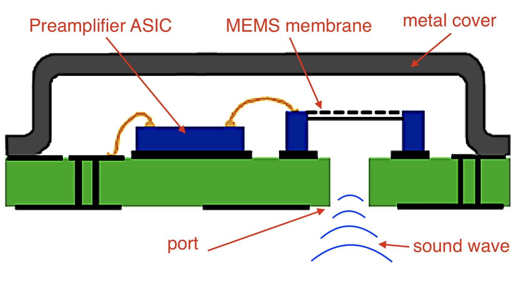
The transducer outputs a PDM (Pulse Density Modulation) digital signal when a clock signal is provided from the MCU.
The PDM signal is used to measure the ambient noise. The MCU uses Digital Signal Processing to calculate the SPL (Sound Pressure Level), which is a logarithmic measure of the pressure level of a sound.
noise data
By no means the microphone is used to sample intelligible voice or audio data, the only sound information transmitted to the USB host are the SPL levels measured over a 125ms time window, as in a Sound Level Meter (decibel-meter).
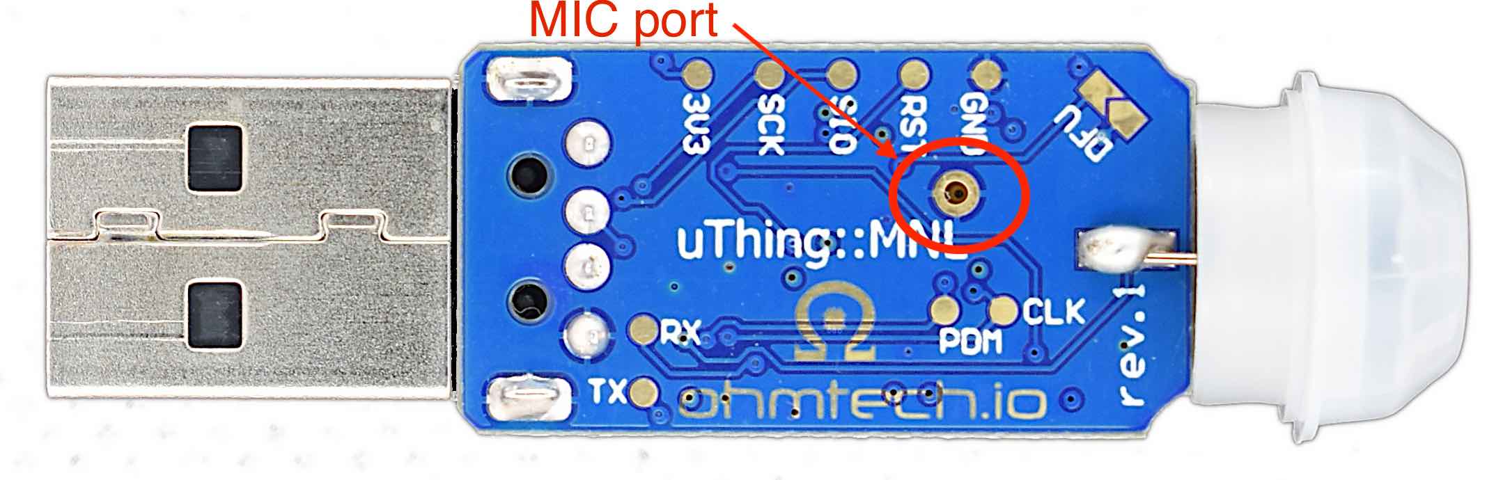
Noise port location
The noise input port is located at the bottom side of the PCB (picture below). Therefore, the orientation of the dongle needs to be taken in account when comparing absolute noise levels.
Sound pressure and distance
Inverse-proportional law
When measuring the sound pressure created by a sound source, it is important to consider the distance from the object as well, since the sound pressure of a spherical sound wave decreases from the centre of the sphere.
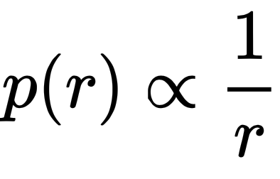
Where "r" is the distance to the sound source and p(r) the sound pressure. This relationship is an inverse-proportional law.
SPL
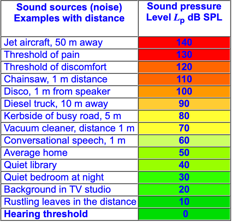
Sound pressure level (SPL) or acoustic pressure level is a logarithmic measure of the effective pressure of a sound relative to a reference value. The reference level is the "human hearing threshold" (0 dBSPL, about 20 uPascal).
As mentioned above, the exact level of the measured SPL depends on the distance to the source, and as well the spectral content of the noise source (how constant the different frequency components are over time), but as a general reference, the table below can provide a rough idea:
dBSPL and dBA
There are several standards that define sound level metering. Some instruments provide the measured output after a frequency-weighting filter, being A-weighting a common one (defining the output as dBA).
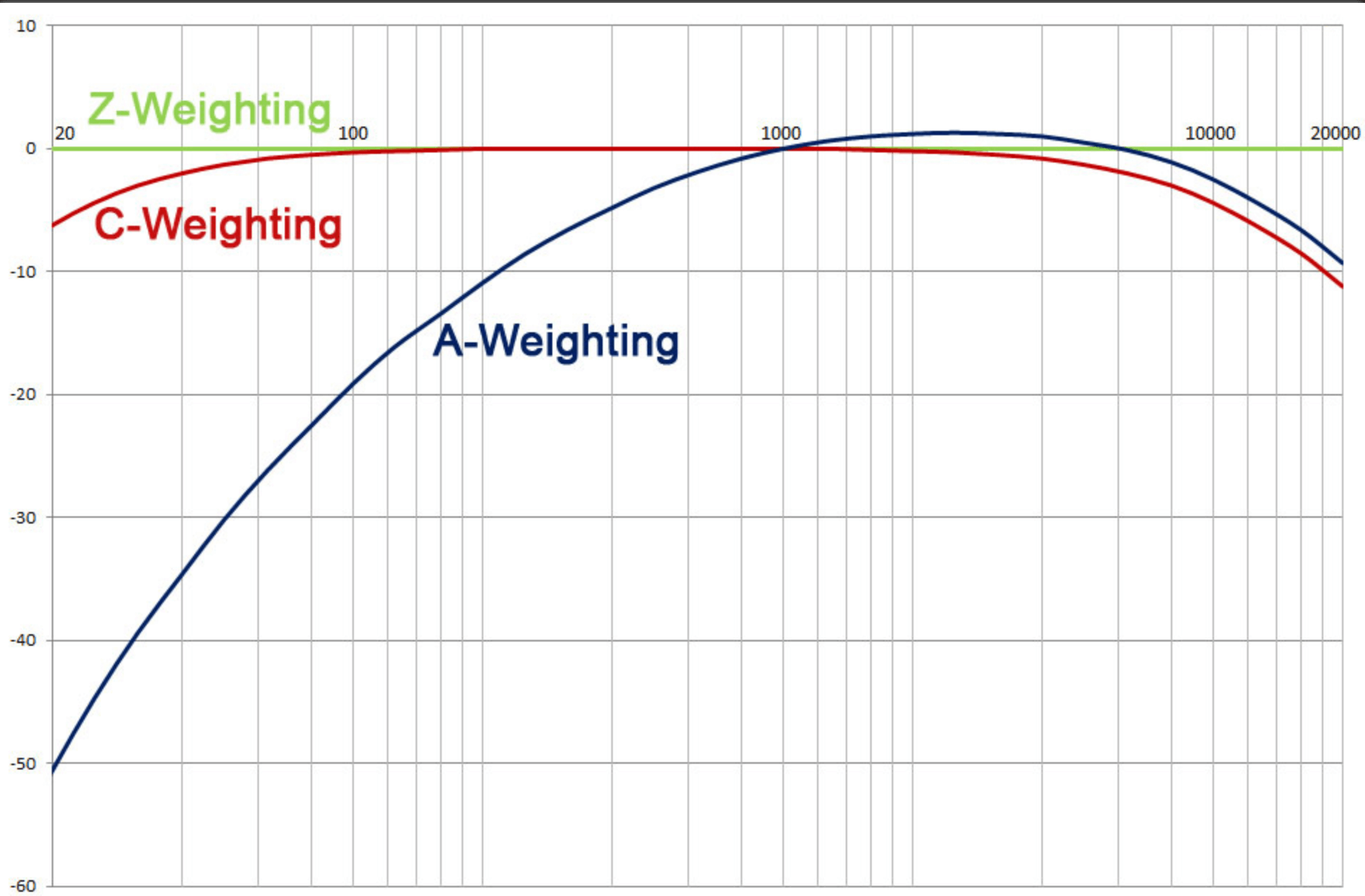
As the A-weighting significantly reduces the importance of low frequency noise sources (i.e. air conditioning, or a diesel engine), uThing::MNL uses equal weighting for all the frequency range between 20Hz and 20kHz (Z-weighting). The output is provided in "dBSPL" units.
Output data
The uThing::MNL will report data on the configured period (every 1 second by default).
On every reporting period, sound data is processed over a standard time window of 125 ms (fast window as usually called by decibelmeter instruments).
The peak (maximum) and base (minimum) levels measured during the aforementioned window are also included on every JSON output.
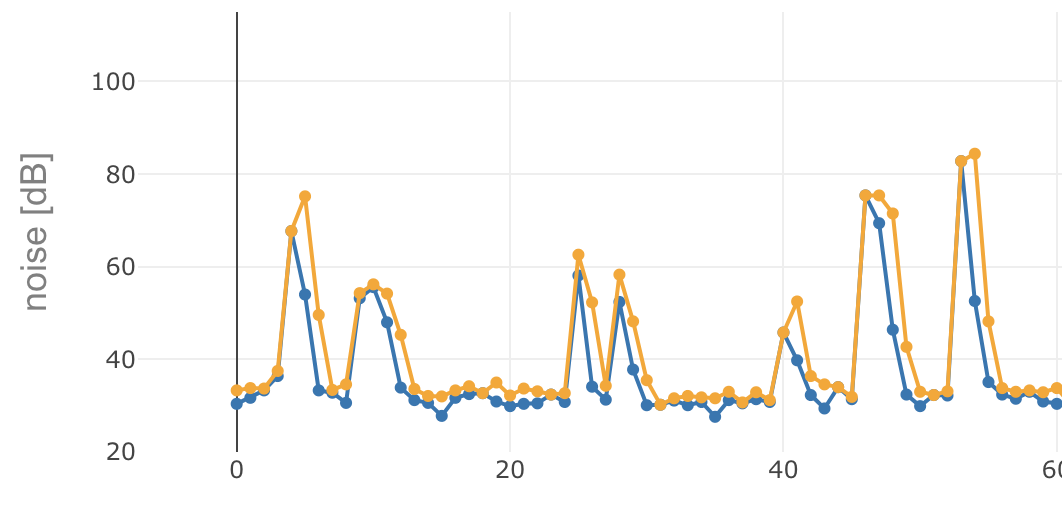
"noise": {
    "rms": 30.8,
    "peak": 33.5,
    "base": 29.4
}
The figure below shows a capture of the Peak (orange) and RMS (blue) values over a period of 60 seconds.